Install Guide
Pebble Plus • RS-485 Bus
RS-485 Wiring & Installation Guide
This page explains the RS-485 standard, recommended cable pairing, bus topology, termination, and waterproof junction best-practices for Pebble Plus sensor runs.
RS-485 quick rules
If you only read one section, read this.
Daisy-chain only (no star)
Run one trunk line from the controller through each junction/sensor in sequence. Avoid star splits and long stubs.
Twist A/B as a pair
Use Cat5/Cat6 or a twisted pair for RS-485 A and B. Keep A/B together for noise rejection.
Terminate at the ends
Pebble Plus includes controller-side RS485 termination as standard hardware. Count the Pebble Plus as one end terminator, and add one 120Ω resistor across A↔B at the final node only.
Keep stubs short
If you branch from a trunk into a sensor, keep that branch short (ideally under 30cm / 12in).
Separate from high voltage
Keep RS-485 away from AC mains, pumps, motors, and long parallel power runs when possible.
Bond shield/drain at one end only
If using shielded cable, do not leave the drain wire floating. Bond it to Ground at the controller end (single-point).
Field wiring standard
These are the install rules that prevent most intermittent communication faults.
Use ferrules on stranded wire
Do not land loose stranded conductors directly under screw terminals where possible. Use ferrules or proper crimp terminations to improve contact reliability and reduce intermittent faults.
Provide strain relief
Every enclosure and junction should prevent cable movement from pulling on the terminal connection. A wire that looks tight can still become intermittent under vibration or handling.
Carry a common reference
When sensors are powered along the same run, keep Ground / common reference continuous end-to-end. Do not rely on RS-485 A/B alone if the installation also shares power.
Label both ends before energizing
Mark A, B, +, and GND at both ends before connecting power. Many field issues come from polarity swaps or mixed labeling between devices.
Keep one polarity standard
Choose one A/B polarity convention and keep it consistent across every Pebble, junction, sensor, and drawing. Never “flip as needed” per node.
Check far-end voltage under load
A sensor can appear wired correctly and still fail if the far-end supply drops under load. Measure voltage at the remote node while the system is energized.
Recommended topology
Pebble Plus uses a trunk cable and IP68 junctions to daisy-chain sensors. A Tee junction is only acceptable when the trunk continues through and the sensor branch remains short.
How to read this:
A Tee junction is acceptable only when the main trunk continues through the junction and the branch to the sensor is kept very short. If one point splits into multiple long branches, that is no longer a proper daisy-chain bus.
Controller (Pebble Plus)
RS-485 A/B + Power in enclosure • TERM (end 1)
IP68 Junction (Straight/Tee)
Trunk continues • sensor stub kept short
Sensor Node 1
Main or Reserve • one tank opening per sensor
Final Sensor Node (Last)
TERM (end 2) • 120Ω across A↔B at last node only
How to read this diagram:
A Tee junction is acceptable only when the main trunk continues through the junction and the branch to the sensor is kept very short. If one point splits into multiple long branches, that is no longer a proper daisy-chain bus.
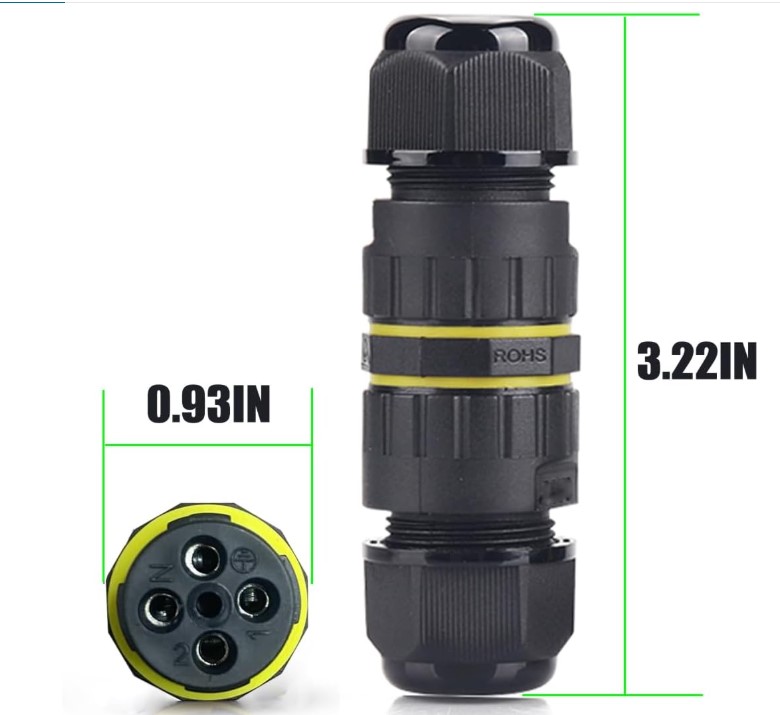
IP68 Junctions:
Use waterproof junctions for trunk continuity. Avoid star wiring. Maintain consistent A/B polarity through every junction.
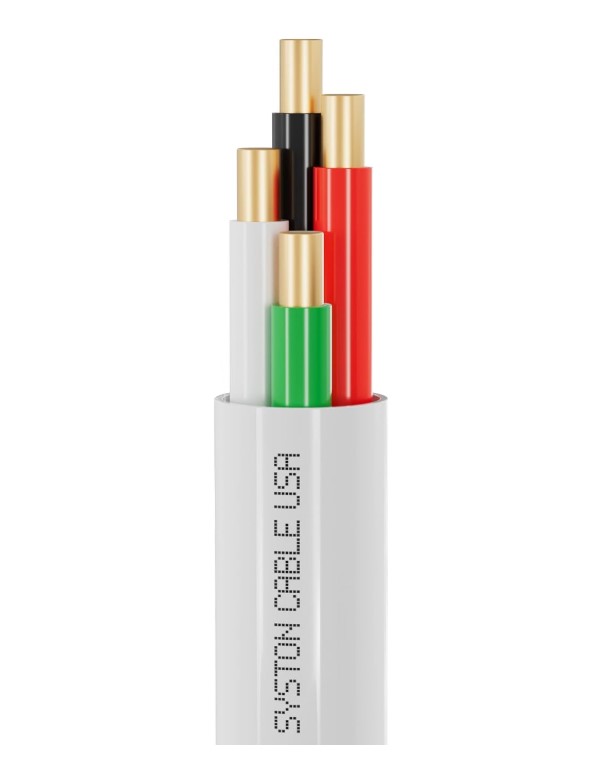
Cable:
Cat5/Cat6 is recommended for RS-485 (twisted pairs). If powering sensors along the same run, ensure adequate conductor gauge to reduce voltage drop.
Topology do / do not
This visual comparison shows the difference between a healthy RS-485 trunk, an acceptable short Tee stub, and a star layout that is likely to cause communication faults.
Pebble Plus is normally installed at one physical end of the RS485 trunk. The controller-side termination is built into the Pebble Plus hardware. Add the second 120Ω terminator at the final node only.
Quick rule:
One continuous trunk is good. A short branch from a Tee can be acceptable. Multiple long branches from one point are not a proper RS-485 bus and should be treated as a star.
Good: linear trunk
Preferred RS-485 layout
Controller → node → node → final node. The communication line stays continuous from one end of the bus to the other.
Acceptable: short Tee stub
Only when the trunk continues through
A Tee is acceptable only if the main trunk continues through the junction and the drop to the sensor stays very short.
Bad: star split
Avoid multiple long branches
If one point feeds several long branches, the layout becomes a star. This can cause reflections, unstable timing, and intermittent communication faults.
Main RS-485 trunk
Healthy node on a proper trunk
Short acceptable Tee stub
Problem layout / star branch
Important:
If the installation truly requires multiple long branches, use a proper RS-485 repeater or hub so each branch becomes its own managed segment rather than a passive star.
Pebble Plus hardware note:
Pebble Plus uses a standard MAX485 interface module with a fitted 120Ω RS485 termination resistor on the controller side. In the normal Pebble Plus layout, this counts as one end terminator. Install only one additional 120Ω resistor at the final node on the bus.
Recommended Cat5/Cat6 pairing
A simple pairing plan reduces noise and installer mistakes.
| Pair | Use | Notes |
|---|---|---|
| Pair 1 | RS-485 A / RS-485 B | Must be twisted together; keep polarity consistent end-to-end. |
| Pair 2 | +12V / GND | Twist power and ground to reduce loop area. Watch voltage drop on long runs. |
| Pair 3 | Spare / future use | Optional: reserved lines for future sensor triggers or expansions. |
| Pair 4 | Shield / drain (if present) or spare conductors | If shielded, bond drain/shield to Ground at controller end only (single-point). |
Tip:
Label both ends of the trunk (A/B and +/GND) before pulling cable. Most wiring issues are polarity swaps or broken continuity at junctions.
Field standard:
For permanent installations, use ferrules on stranded wire, maintain continuous Ground/common reference when power is shared, and provide strain relief at every enclosure and junction.
Termination & stability
If readings are unstable or missing nodes, check termination and topology first.
Where termination goes
Pebble Plus includes the controller-side RS485 termination resistor as part of the standard hardware. Treat Pebble Plus as one physical end of the trunk, and place one 120Ω resistor across A↔B at the final node only. Do not add another controller-side terminator unless the built-in termination has been intentionally removed or disabled.
Avoid long stubs
A long branch acts like an antenna and causes reflections. Keep sensor stubs short and keep the trunk continuous.
Bench vs field note:
A very short bench setup may appear to work without proper end termination. Final installations should still follow the full trunk standard: end-to-end daisy-chain, short stubs, and 120Ω at the two physical ends only.
- A/B swapped: If one node reads and others don’t, a junction polarity swap is common.
- Star wiring: If one point splits into multiple long branches, the bus can suffer reflections and intermittent communication faults even if the cable looks neat and all nodes are powered.
- No termination: Symptoms: unstable readings, dropouts, only works at short distance.
- Floating drain: A floating shield/drain can inject noise. Bond at one end.
- Power drop: Long power runs on small gauge cause sensors to brown-out. Check voltage at far end under load.
Dead communication checklist
Use this in order before replacing hardware.
1. Check power at the far node
Measure supply voltage at the remote sensor or module while powered. Do not assume the voltage at the controller is the same at the far end.
2. Check A/B polarity through every junction
One flipped junction is enough to make a node disappear. Confirm A stays A and B stays B end-to-end.
3. Check continuity and connector pressure
A wire can look properly landed and still make poor contact. Re-seat conductors, check ferrules, and inspect for partially clamped strands.
4. Confirm termination placement
Terminate only the two physical ends of the trunk. Too much or too little termination can both cause unstable behavior.
5. Isolate the bus
Disconnect branches or devices until one known-good node responds. Then reconnect one segment at a time to find the fault.
6. Recheck topology
If communication returns when wiring is simplified, suspect a star layout, long stub, poor junction, or excessive branch length.
Reminder:
A temporary disconnect / reconnect may restore communication, but that usually points to a wiring, contact, grounding, or topology issue rather than proving the original installation is stable.
Pebble Plus RS-485 ecosystem
Pebble Plus can read native RS-485 sensors directly, and can also expand through RS-485 modules for analog sensors and tank-top switch monitoring.
Native RS-485 sensors
Preferred for new installations. Sensors such as Pebble-A01, Pebble-A02, and Pebble-300 RS485 connect directly to the Pebble Plus RS485 bus.
Analog module
Use the Pebble Analog Module when the field sensor outputs voltage or current, such as 0–10V or 4–20mA. The module converts those readings to RS485 data for Pebble Plus.
Tank-top switch module
Use the Pebble Tank Top Module for tank lid switches, float switches, dry contacts, or open/closed alarm states. One module can monitor multiple switch inputs.
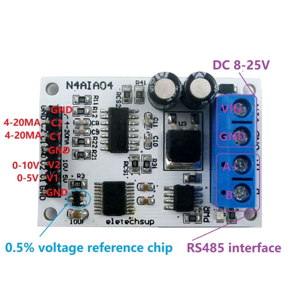
Pebble Analog Module:
Connects compatible analog-output sensors to Pebble Plus. Useful for retrofit installations, existing pressure transmitters, PLC-style environments, and 4–20mA / voltage-output sensors.

Pebble Tank Top Module:
Reads tank-top switches, dry contacts, lid-open states, float switches, and alarm contacts over the RS485 bus. Recommended when the installation needs access/security or state monitoring in addition to level measurement.
Selection rule:
For new level-sensor installations, choose native RS485 when available. Use the analog module when the sensor or existing site equipment only provides analog voltage/current output. Use the tank-top module when you need open/closed switch monitoring rather than level measurement.
Sensor-specific notes
These sections are what the “View specs” button links to.
Ultrasonic, RS-485 option

Tank-top ultrasonic. Confirm you purchased the RS-485 output variant for bus use.
Install notes
Mount at tank opening. Keep bus daisy-chained. If using a Tee junction, keep the stub to the sensor short. Terminate at the final node only.
What to verify
Output type (RS-485), supply voltage, and that A/B polarity is consistent across every junction.
Ultrasonic, 3cm blind zone

Variant-based outputs. Confirm you received the RS-485 version if deploying on the Pebble Plus bus.
Install notes
Respect the blind zone near the face of the transducer. If using RS-485 variant, follow the same bus rules: twisted A/B pair and end termination only.
What to verify
Variant output type, supply voltage, and stable power at the far end under load (avoid brown-outs).
Hydrostatic / Submersible, RS-485 option
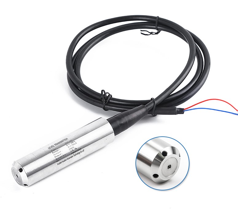
Submersible transmitter family. Confirm RS-485/Modbus variant (many are also sold as 4–20mA).
Install notes
This is not a tank-top ultrasonic. It installs in the tank. Confirm output type and supply requirements before wiring to the RS-485 bus.
What to verify
Output (RS-485 vs analog), bus addressing (if applicable), and waterproof strain relief at entry points.
Back to Device Instructions
Tip: link directly to a sensor section using anchors, e.g. /site/rs485-guide#dypa01a