Set up the portal before the installer goes on site.
This guide covers the website-side setup: create the Monitoring Profile, link or create the Main Tank, choose the sensor type, and add optional reserve tanks or tank objects only when needed.
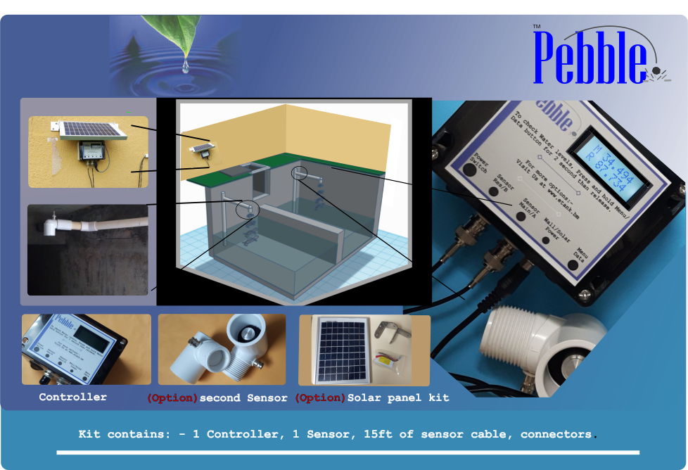
The setup path
Monitoring Profile
Create the portal record for the physical Pebble Monitor.
Main Tank
Link or create the Main Tank from the monitoring profile page.
Sensor Type
Choose ultrasonic, submersible, or manual input where appropriate.
Reserve Tank
Add only when the site has a real reserve tank.
Tank Objects
Use only for shapes or structures that change usable capacity.
Install & Link
Move to the physical install guide after the portal is ready.
Video setup help
Short setup videos are available in the system to help with Main Tank setup, Reserve Tank setup, and additional tank measurements. Videos are available after login and load only when clicked.
Setting up your first tank Short video
Watch the first-tank setup flow: select the site, choose the tank shape, enter the tank measurements, and save the Main Tank.
Add another tank and monitoring profile Short video
Watch how to add another tank and connect it with a monitoring profile so the portal is ready for device setup.
Required portal setup
Complete these items before using the physical Pebble Monitor setup screens.
The Monitoring Profile is the portal record used for tank reporting. Create this first so the system can generate the Monitoring Profile Serial and Link Code.
- Choose the Complex and Building.
- Select the physical site timezone.
- Save the monitoring profile to generate the Monitoring Profile Serial and Link Code.
- Keep the Link Code available for the physical Pebble Monitor setup.
Action
Start here if this is a new installation. If the monitoring profile already exists, open Monitoring Profiles and continue from the existing record.
The preferred workflow is profile-first: open the Monitoring Profile, then link an existing Main Tank or create a new Main Tank from that monitoring profile page.
- Main Tank is the primary tank being monitored.
- Sensor A / reading 1 is the Main Tank.
- Tank/profile linking should be managed from the monitoring profile page.
- Avoid changing the monitoring profile assignment manually from the tank update form.
Ultrasonic distance sensor
Mounted above the water and measures distance down to the water surface. Height of Sensor can be different from High Water Overflow.
Submersible level sensor
Installed in the fluid and reads level/depth. Sensor Height is automatically treated as equal to High Water Overflow.
Open submersible guideBefore the installer starts the physical setup, confirm these items are done:
- Monitoring Profile exists.
- Monitoring Profile Serial is visible.
- Link Code is visible.
- Main Tank is linked or ready to be linked.
- Sensor Type is selected correctly.
Tank setup reference
Choose the tank shape that matches the real tank, then enter the inside measurements. Keep the detailed shape rules on the tank-specific manual pages where possible.
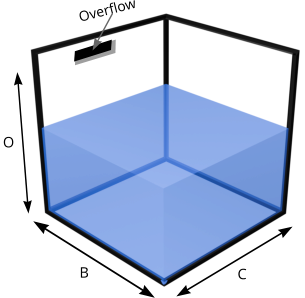 Square / Rectangle
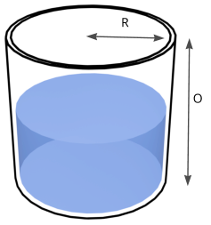 Vertical Cylinder
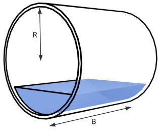 Horizontal Cylinder
Optional setup
Reserve Tanks are added only after the Main Tank exists and the Main Tank is marked as having a reserve.
- Sensor B / reading 2 is the Reserve Tank.
- The Main Tank must have “This tank has a reserve” enabled first.
- Reserve Tank also has its own Sensor Type: ultrasonic or submersible.
- Manual Level Entry cannot be used with a Reserve Tank.
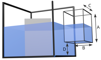 Connected Space
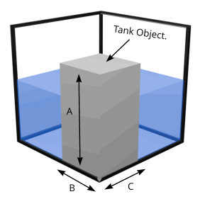 Block / Bay
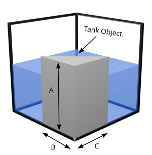 Wedge
Wedge
Use Tank Objects only for internal shapes, connected spaces, side spaces, blocks, wedges, or objects that change usable capacity.
- Enable “Has additional tank measurements” on the Main Tank before adding Main Tank Objects.
- Enable “Has additional tank measurements” on the Reserve Tank before adding Reserve Tank Objects.
- Use ADD for connected space that holds fluid.
- Use SUBTRACT for objects or shapes that reduce usable capacity.
Use this when the selected Pebble installation uses RS485 sensors/modules or an approved Sensor Bus v1 adapter workflow.
- Each RS485 device must have a unique address.
- Use the M12 Sensor Bus guide for connector/component identification, linear-trunk topology, short sensor drops, far-end termination, addressing, and troubleshooting.